Introduction
Over the length of the semester we will apply the concepts and techniques presented in this course to a redevelopment project. The project will focus on locating, sizing, detailing and documenting a number of site-scale, water management programs.
Site Location
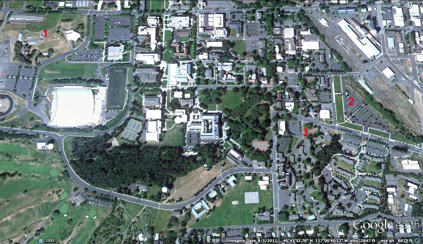
Left: Aerial view of the University of Idaho campus, site 1 is the project site.
The site is called Poultry Hill and is located in the western part of the University of Idaho campus. Located at the near the Kibbie Dome parking lot and Perimetr Drive. The site is composed of a summit with a few steeply sloping areas. The existing buildings have nearly reached the end of their life. In fact, some of the buildings are currently unoccupied or used as storage.
Site Planning
Master plan alternatives are provided on the course One Drive site. Choose one to use or modifiy for the purposes of this course. Note on the master plans that three building footprints of proposed student housing structures have been adopted. Your team can re-distribute these buildings if you like. The semester project in this class will require that you develop parking, planting, irrigation, rough grading and water treatment plans. The water treatment plan will be supported by three dimensional models an sections to illustrate the concept and detail the construction requirements. Finally, and most important for this course, is the documentation of the performance of the landscape for water management and water quality. Download the AutoCad base from the One Drive course folder.
Tasks
The semester-long assignment is divided into several tasks associated with the topics of the course.
Download the project site base and contours. Combine them into a single file. Find the files on the course One Drive site.
Task 1 - Site Inventory and Analysis
Work in teams of five persons or less. Print the site base sheet (with contours) and annotate it during your site visits to document the existing conditions or enhance the work of a Larc 251 student. Visit the site with a camera and a base sheet to familerize yourself with the site conditions.
From contours and spot elevations find the greatest difference in elevation on the site.
Gather data for our stormwater calculations - Determine the length and slope percentages for the longest path that water follows to reach each stormwater outlet at the bottom of the hill. Note the location of grade breaks and surface cover on the site base.
Task 1 Deliverables
1. A new project base sheet that includes the following elements:
- Existing contours, low points, high points
- Street curbs, names
- Existing manholes, catch basins, storm sewer lines
- Existing trees and shrub masses.
- Outside the boundary of the site show about 50' of existing buildings, roads, parking, open space, etc. for context.
2. Presentation template
In InDesign prepare a 24" x 36" sheet with drawing scale, north arrow, project title, student names, professor's name, semester and year. Save the sheet as a template to receive Adobe Illustrator and other assets.
3. Site inventory and analysis
Show slopes greater than 25% and slopes 0-5%, Time of Concentration line with distances, land cover and slope gradients, square footage of the site, low and high points, grade breaks, soil type boundaries, soil hydrologic soil groups, precipitation average by month, existing trees and shrub masses, existing area of compacted soil, outline of existing parking areas. Illustrate the site conditions with at least 10 photographs of the site elements and note the opportunities and constraints that they depict. Create your analysis sheet in InDesign and export as a PDF and submit with the file name SiteInvTeamOne or Two. See the course calendar for the due date.
Task 2 - Building and Drainage Concept
Working in teams of five or less, make any modifications to the master plan. Calculate the proposed population of the site and the number of dwelling units per gross acre (our target is 50 units per acre). Locate and size parking to provide 350 spaces. Assume 270 square feet per parking space (including aisles). Locate parking areas. Do not draw the individual spaces or associated planting areas for this task. Locate and size all walkways and plaza spaces. The detailed design of the plazas will be done later.
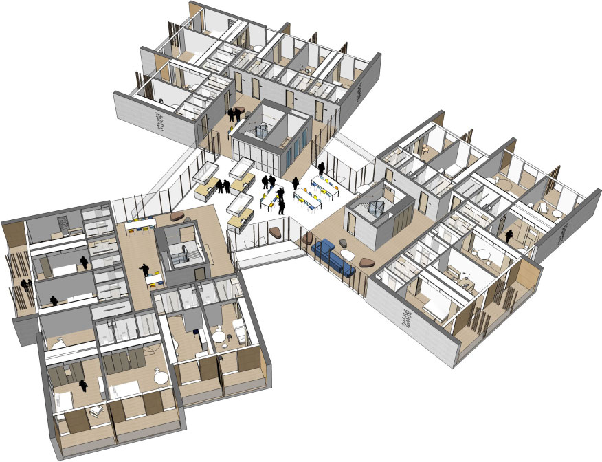
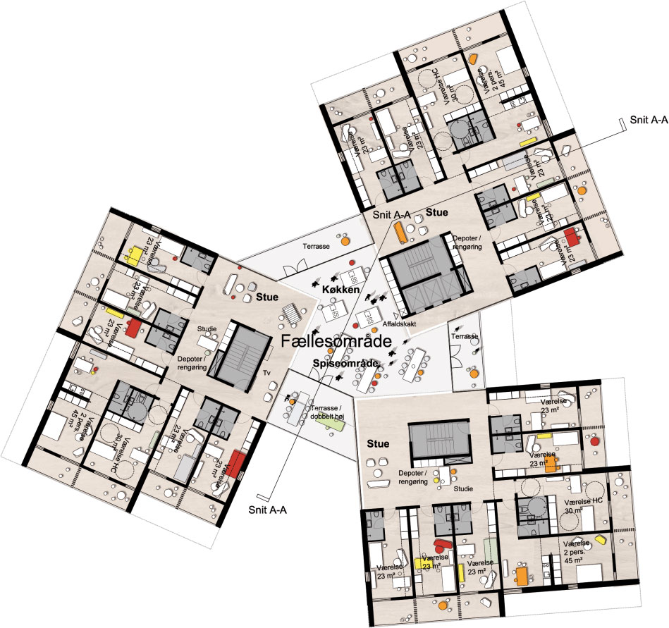
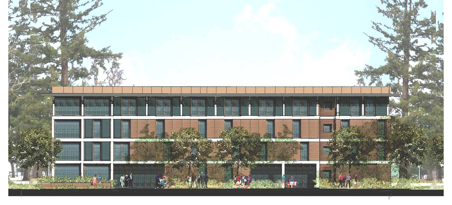
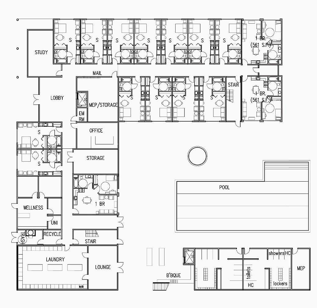
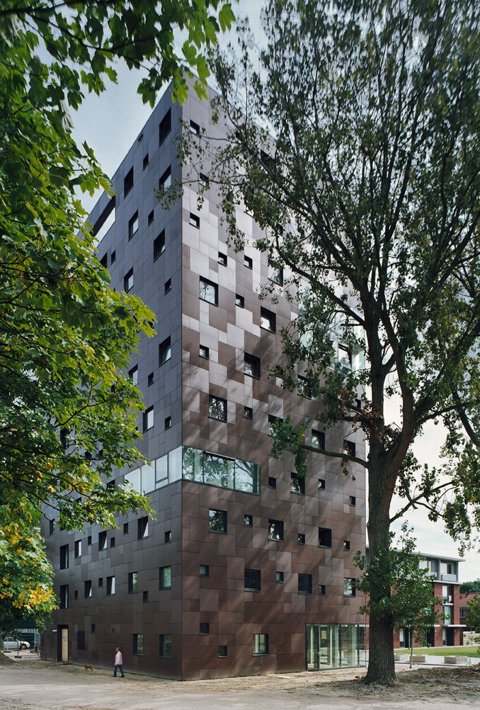
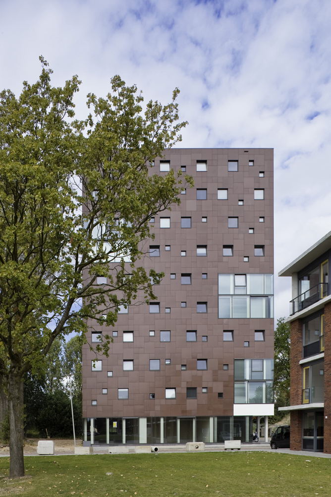
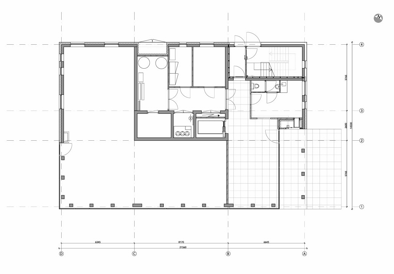
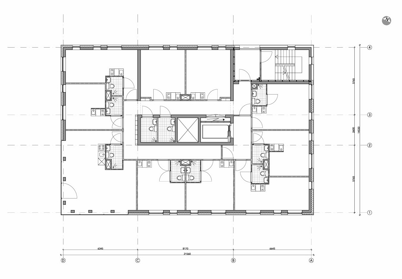
Below are a series of images and plans for student housing. Adopt these floor plans and distribute them where most appropriate on the site (note that the University of the Pacific option can be adapted as an earth sheltered building. Define the number of floors in the buildings shown to meet your purposes. Trace the images in AutoCad and rescale them to match the scale of your master plan (1" = 40'). Then copy the building footprint and place it to create arrangements that enclose exterior spaces. Then define the paved and landscaped space. Calculate the are of the plaza paving for each building group.
University of Southern Denmark Student Housing
University of the Pacific McGeorge Student Housing in Sacramento
University Student Housing in Sweden
Task 2 Deliverables
1. Create an Adobe Illustrator file of an imported AutoCad Base. In the illustrator file generate professional graphics showing: proposed buildings (define building by number and stories - R1/3), proposed cut and fill slopes, flow arrows indicating drainage around each building and across each parking area.
2. Create a table in InDesign that documents the project size (acres), population, number of dwelling units per gross acre, number of parking spaces and the area of each lot (number the lots L1, L2 etc.) and the square footage of each roof (number each roof, R1, R2, etc.), square footage of each plaza (number each plaza, P1, P2, etc.), total walkway area (see sample below).
| Project Data | |||||||||
|---|---|---|---|---|---|---|---|---|---|
| Site size | |||||||||
| Population | |||||||||
| DU/gross ac | |||||||||
| Walkway SF | |||||||||
| 1 | 2 | 3 | 4 | 5 | 6 | 7 | 8 | 9 | |
| Parking lot spaces/SF | 15/5,250 | 21/7,350 | |||||||
| Roof SF | 10,000 | 20,000 | 10,000 | ||||||
| Plaza SF | 15,000 | 30,000 | 10,000 | ||||||
3. Import the Ai file and table into the InDesign presentation template. Title the sheet as "Building and Drainage Concept". Save as a PDF file and submit as BldgConceptTeamOne or Two. See the course calendar for the due date.
Task 3 Pre-Development and Conventional Post-Development Runoff Rate and Volume
In teams of two use the TR-55 Program to generate the pre-development peak cubic feet per second runoff for a 1" event, the 2-year, 10-year and 25-year 24-hour storms. From the TR-20 report find the runoff depth for each of these storms. Calculate the pre-development runoff volume for each storm.
Next generate the same information for the post-development condition. Assume all roof, streets, plazas and walkways are impervious. Calculate the post development runoff volume for each storm. Calculate the difference between the pre- and post-development runoff volumes for each design storm.
Note: for the off-site contribution of stormwater on Taylor Street assume meadow grass in good condition for the pre-development condition. For the site assume the same cover for the valley area and woodland for slopes over 25%. Model the woodland and grassland area as separate sub-drainage areas since the runoff Curve Numbers differ by more than 5.
Task 3 Deliverables
1. Create a table using InDesign displaying pre- and post-development results. Display peak runoff CFS, runoff depth in inches, time of peak runoff, runoff depth in feet, runoff volume in cubic feet, the difference in pre- and post-development runoff volumes in cubic feet.
2. Plot an outlet hydrograph showing the pre- and post-development condition for the 1" (water quality storm) event. Import the plot into Illustrator and redraw the image for presentation. This sheet will probably not be full. We will add information to it when we complete the next task.
3. Import the table and Ai file into the InDesign presentation template. Title the sheet as "Pre- and Post-Development Runoff and Volume". Save as a PDF file and submit as TR55 LastNames of Members. See the course calendar for the due date.
Task 4 - Water Harvesting
Locate the runoff volume difference between pre- and post-development for the water quality storm from the previous task. This is the on-site storage target for a modified site design that incorporates green infrastructure elements that manage and treat stormwater. This task will focus on water harvesting to achieve two purposes. One is to reduce the consumption of potable water by substituting roof runoff for non-potable uses, such as toilet flushing. Second, the collection of roof runoff and using it in the building removes it from the stormwater volume. There is a potential conflict of goals here. Green roofs are valuable for reducing roof runoff and improving building energy performance. However, specifying green roofs reduces the amount of water available for harvesting for reuse and may reduce its quality. Green roofs are less effective, from an energy standpoint, on tall buildings. Therefore, you might specify white roofs on the tallest buildings and green roofs on others.
Decide on a green roof strategy and then working as individuals calculate the potential volume of water that you can collect from each of the roofs each month. Next estimate the amount of water needed to flush the toilets in the buildings each month. This will require an occupancy estimate for the summer months. We will attempt to get this from the UI facilities management department. Determine the storage volume required to serve the buildings during the months of low rainfall.
In addition to the water harvested and reused there is contaminated grey and black water that we will collect and treat on-site. In this task you are to determine the monthly volume of greywater and blackwater that will require treatment. We will use hybrid wetlands to treat this water and make it available for reuse in irrigation.
Task 4 Deliverables
1. Produce a table using InDesign displaying the required monthly volume and the harvesting potential for each building. Display the storage volume required for each building and the volume of runoff (water not used in the building).
2. Produce a section or sketchUp model of a typical storage tank solution that incorporates the tank into the landscape design (aesthetic treatment). Provide the cost of the tank and the cost per gallon stored per year.
Add this information to the TR55 sheet and resubmit.
Task 5 - Pollution Treatment
This task requires you to work independently again to redesign the parking lots to achieve two goals. First, the lot design must provide for shade over 50% of the surface area at noon on June 21, ten years after construction. Assume tree diameters at 60% of full maturity.
Second all of the runoff from the parking area must receive treatment to reduce non-point source pollution. There are several design options that will meet this goal to varying degrees. Often different techniques are combined to achieve reductions in runoff rate, runoff volume and pollution. For example the parking bays might be constructed of permeable paving (permeable concrete, permeable asphalt or unit pavers) to slow runoff and begin water quality improvement. The outflow might be directed to a bioretention basin or stormwater wetland for additional detention, infiltration and water quality improvement. You are to devise a treatment sequence and calculate the reduction in the runoff peak, infiltration volume, and expected water quality improvement.
This is a complicated problem since it requires that you acquire research data documenting the performance of various stormwater treatment landscapes compared to the pollution levels of conventional (untreated) runoff.
Task 5 Deliverables
1. Create a table identifying the pollution concentrations and load that you expect in the parking lot runoff and the concentration (or percent reduction) of the contaminants due to the landscape treatment. Also, indicate the water quality standard for each contaminant if it has been set.
2. Create a table displaying the runoff volume for the water quality storm and the size of the landscape elements required to contain and treat it. Note the anticipated outflow.
3. Produce a plan that places and correctly sizes stormwater treatment landscapes associated with the parking areas. Produce a plan view enlargement and a section or sketchUp model of the treatment landscape. Include construction details and specifications critical to the effective performance of these landscape elements.
4. Assemble the products on the InDesign presentation template. Title the sheet as "Pollution Treatment". Save as a PDF file and submit as Treatment LastNames of Members. See the course calendar for the due date.
Task 6 - Stormwater Retention and Detention
This task requires you to work independently and requires that you return to tasks 4 and 5 to recover the volumes that leave the harvesting and treatment elements. These will continue through the landscape to either infiltrate, evaporate, become used in irrigation or flow through the project outlet (storm sewer). However, the water quality storm volume must be retained entirely on-site.
Retrieve the water quality volume from a task 3. While the parking lot water has been treated once, runoff from the landscape also contains contaminants. There will also be runoff from walkways and plazas that contribute runoff. Find research data that indicates the contaminants expected from the landscape. Repeat the exercise from task five to locate, size and determine the reduction in contaminants from the landscape elements that you select. These could be stormwater wetlands or bioinfiltration basins or retention basins. As in the last task, provide plan, section and sketchUp models to illustrate the design and critical construction elements. Again note the outflow from the landscapes that you specify.
Task 6 Deliverables
See task 5 for the required products. Assemble the products on the InDesign presentation template. Title the sheet as "Pollution Treatment". Save as a PDF file and submit as Retention LastNames of Members. See the course calendar for the due date.
Task 7 - Blackwater and Greywater Treatment
This task requires you to work independently. You have already calculated the amount of wastewater produced by the building residents. Retrieve these amounts from task 4. Locate the required septic tanks and wetland treatment stages. The treated greywater can be reused for toilet flushing in the buildings if the volume of water from roof harvesting is insufficient. Otherwise it can be used for irrigation or to sustain wetland for aesthetic and habitat purposes. Treated blackwater can be used for habitat or irrigation. Once you have decided on a treatment and reuse strategy locate and size the treatment landscapes based on the environmental engineering literature. Be sure that stormwater runoff does not flow into these treatment wetlands. Use Task 4 as your guide to the processes and products required for this task.
Task 7 Deliverables
Assemble the products on the InDesign presentation template. Title the sheet as "Wastewater Treatment". Save as a PDF file and submit as Wastewater LastNames of Members. See the course calendar for the due date.
Task 8 - Secondary Benefits
The stormwater landscapes that you have proposed in the previous tasks include benefits, such as aesthetic scenery, wildlife habitat and irrigation supply. This section asks that you reconsider your design for the project in order to maximize these secondary benefits. For example, you should develop a planting plan dominated by native plants, especially in areas adjacent to the habitat corridor through the site. Similarly, native and drought tolerant plants can minimize that amount of water needed for irrigation.
After selecting the planting pallet and completing the planting plan, determine the irrigation volume required to achieve a thriving and attractive landscape. Use the research from the Water Use Classifications of Landscape Species research from California. Right click the link to download the PDF file to your computer. We will use the Region 1 data since it matches Moscow's summer conditions. Determine the water needs of each plant in your palette and for the total landscape. How much of this need can be provided by water that you store on-site in cisterns or ponds?
Task 8 Deliverables
Planting design
Plant Water Need spreadsheet.
Volume of potable water conserved through substitution of non-potable water for toilet flushing and irrigation.
Task 9 - Irrigation Design for Water Conservation
We can engage a number of irrigation design practices and equipment specifications that will conserve the precious water we collect on-site or pump from the aquifer. A potential resource that mat be available since the University of Idaho is adjacent to the wastewater treatment plant is the reuse of sewage effluent for irrigation.
Task 9 Deliverables
Water a water conservation plan associated with irrigation.