I started this project to develop a low cost automatic irrigation system for home gardens and landscapes. The main design criteria is to keep everything simple as possible and still keep from killing the lawn or the wive's flowers. In addition I would like to keep all the materials to build the system available at the local hardware store.
I started working on this project in January of 1994. It's been placed on the back burner, because of the extra load on my day job, many times. You can be sure I wore out a lot of hose by moving it around since then. But, things are coming together. This winter, 2001-2002, I plan to run a greenhouse test with the existing hardware. By spring I'll know if the system can be trusted on my wives flowers.
Project Development
I decided
to use gypsum block moisture sensors for this project. They are
cheap, fairly accurate, easy to obtain or make, and reliable.
Although they may need to be replaced after time, less total labor
is needed to maintain them compared to tensiometers. They operate
electrically; therefore, they are easily interfaced to a computer
without the addition of transducers.
Gypsum Block Conductors
In
order to save money and time, we made our sensors. All of the
materials are available locally, and they take little time to
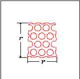
produce. The first material needed is the conductor. We used a
perforated stainless steel plate 0.060 inch thick. I don't know
the exact alloy of this stainless steel plate. It was purchased
from the scrap pile at Pacific Steel. We cut the plate into one
inch square pieces as shown below.
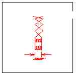
Two of these 1 X 1 inch plates are held 1/4 inch apart with a 1/4 inch diameter acrylic, solid, rod, see the figure below. The plastic rod is held to the screens by heating the screens with a propane torch and pressing the rod to it, melting the plastic, slightly, thereby bonding it to the metal. The figure below shows the side view of the screens held 1/4 inch apart with the two plastic rod spacers. One plastic spacer is placed toward the top, wire end, of the screens at the corner, the other at the opposite lower corner.
Four feet of #24 AWG wire is silver soldered to each screen. The wire used on the prototype is salvaged telephone cable. The two wires of each conductor pair have a different color insulation to tell them apart, making measurements consistent. The wires are left twisted to reduce electromagnetic noise.
Encapsulating in Gypsum
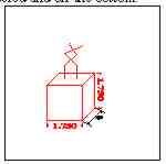
The
screen assembly is then placed in a 1 3/4 by 1 3/4 by 3/4 inch
rectangular mold. and encapsulated in plaster of Paris. The
plaster of Paris brand name is, Bondex Plaster of Paris, item
number 53005, manufactured by RPM Bondex International Inc., 3616
Scarlet Oak Blvd., St. Louis, MO 63122. We used the mixture
recommended on the package, two parts plaster of Paris to one part
of water. The mold was made of paste board, an old cardboard box,
without a coating of mold release. Each mold had eight chambers.
An 8d nail secured to the top of each chamber, in tight holes
punched into the 3/4 inch side of the mold, held the lead wires to
keep the screens centered and off the bottom.
After pouring the plaster of Paris into the mold containing the screens, we let it dry at room temperature for 24 hours. Then the individual blocks were removed from the mold, the figure below shows the completed block. What paste board material that stuck to the sides of the block was removed by lightly scraping with a knife. Finally, we inspected the block for air holes, exposed metal, and electrical continuity. Each block received a unique number for identification.
AC Ohmmeter
The equipment we decided to use to read the gypsum block is an
alternating current (AC) ohmmeter. An AC ohmmeter minimizes the
effects of the field currents in the earth, and also any currents
generated from electrolysis in the sensor.
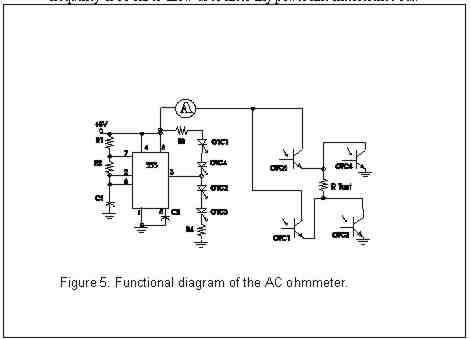
Instead of
designing a sine wave oscillator, amplifiers, and regulator for
the AC ohmmeter, I decided to use a transistor switching circuit
used to control the direction of direct current (DC) motors. While
researching such a circuit I came across a unique implementation
in the July 5, 1974 issue of EDN Magazine, page 70. It uses four
opto-isolators and a 555 timer to give an AC square wave, see
figure 5 for a functional diagram.
The circuit is
built on a Radio Shack no. 276-147, perforated, prototyping board
with a copper pad on one side. The holes are on 0.1 by 0.1 inch
centers. The circuit and battery are enclosed in a Radio Shack no.
270-222 plastic project case, that is 4 5/8 inches long, 2 9/16
inches wide, and 1 9/16 inches deep. Figure 7 shows the face panel
of the AC ohmmeter.
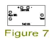
There's no power switch. The spring loaded test button applies power to the circuit and gypsum block. Therefore, power is only used when making a test and not while hooking up wires or carrying the ohmmeter from block to block, extending battery life.
Gypsum Block Calibration
When I was satisfied with the operation of the measuring
device it was time to calibrate the gypsum blocks. Gypsum blocks
respond to soil moisture tension. Most gypsum block calibration
procedures are based on gravimetric moisture, hence percent water
by weight. You can get soil water retention curves for the soils
in your area from most local land grant universities. These curves
will show soil water tension verses soil water percent by weight.
My objective is to keep the soil water between field capacity and
wilting point. One some plants I would like to keep the moisture
close to field capacity so we can get the maximum growth. While on
others, like landscape trees and some house plants, we would like
to keep the water tension above the wilting point but not
necessary at field capacity. I'll calibrate the gypsum blocks from
a saturated moisture level to a very dry level. Then, use the soil
water retention curves to locate the sensor reading to the water
tension. On my soil, field capacity is about 40% water by weight,
and wilting point is about 17%.
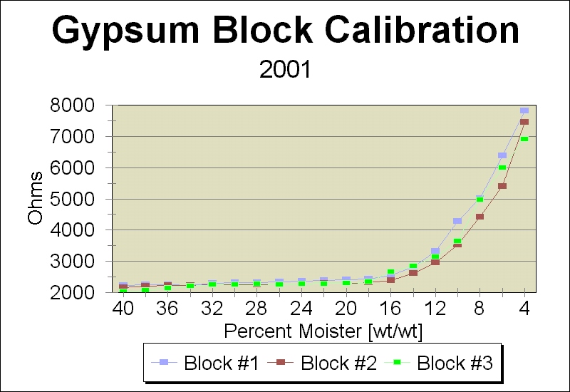
I used the standard method of gypsum block calibration. First I soaked the gypsum blocks for a couple of days in distilled water. Second, a known weight of soil was placed in three cans with the soaked gypsum block buried about midway in the soil. Third, a volume of water to make 40% by weight was added to the can. I got the total weight and set up a spreadsheet to calculate the water percent by the loss at each weighting. The curve below shows my results.
Calibration Results
As
you can see from the graph, all three blocks had about the same
shape of the resistance curve. At the wilting point the slope of
the resistance curve really increases. This point would be easy to
measure. While near the field capacity the curve's slope is nearly
flat.
What's Next
Well it looks like the the curve is too flat to use gypsum
blocks at near field capacity, around 35% moisture. Watermark
granular matrix sensors work good at high moistures but are more
expensive than gypsum blocks, but are poor at low water levels. An
ideal system would include both types of sensor. The Watermark for
high near field capacity water levels, and the gypsum block for
near wilting point readings. I'm going to try to increase the
frequency of the AC ohmmeter and see if I can get a little more
resolution at the higher water levels.
Back to top of page Back to Chuck's Home Page AEC Systems